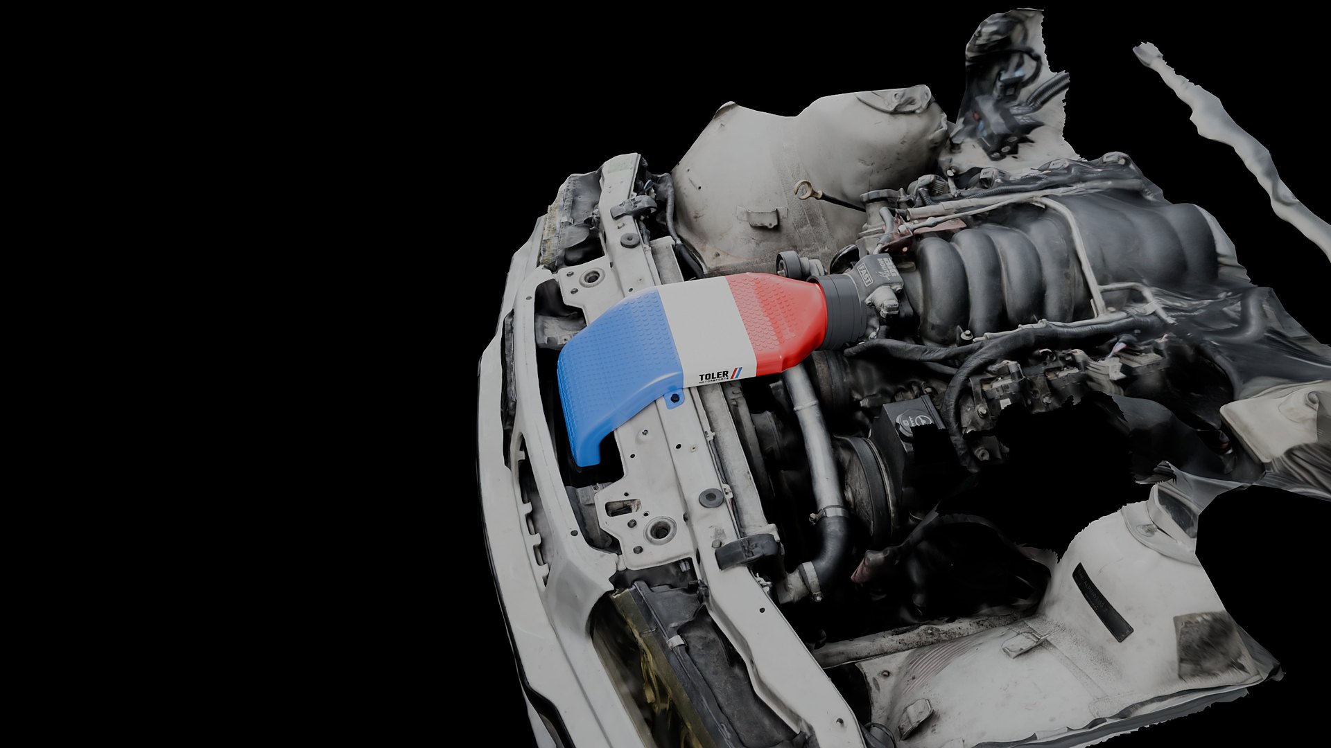
Designed on the scan
Every surface is modeled against a 3D scan of the car, so clearance is known before the part exists.
Intakes, cooling, aero and chassis parts, each fitted to a 3D scan of the car it is built for and checked with real numbers.
The same scan, design, simulate and test process works on any car.
Cold air intakes and airboxes shaped around engine swaps that off the shelf kits never planned for.
Brake cooling and radiator ducting that route air where it is needed, sized from the real openings.
Splitters, flares, vents and louvers fitted to the actual body lines of the car.
We scan your car, design the part, and deliver files or finished parts.
Every part is checked with calculations and simulation before a single layer goes down. Here is what that looks like on the E36 ls swap twin filter cold air intake, taken straight from the CAD and the scan.
Section speeds are continuity, V = Q / A, through 115 sections cut from the CAD. At 676 cfm, a 6.2 L LS3 at 6,500 rpm, the peak is 44 m/s in the duct against 50 m/s in the 90 mm throttle bore. Airflow scales with rpm at the same volumetric efficiency. Particle paths are a visualization, not a CFD result.
Every surface is modeled against a 3D scan of the car, so clearance is known before the part exists.
Every part starts from a scan of the car it is built for, so the same process works on a European sedan, a Japanese roadster, a truck or a one off build.
The chassis, engine bay and body are 3D scanned, so every part starts from the real car instead of a drawing or a forum measurement.
Parts are modeled in CAD directly against the scan and checked for clearance at every mounting point.
Flow area, air speed, clearance and weight are calculated for every part, and aero parts are run through wind tunnel simulation.
Prototypes run on our own race car with logged data. A part is released only after it holds up to heat, vibration and repeated sessions.
Send your year, make, model and engine, and what you want to solve. We will tell you if it is a good fit for a scan and a custom part.
Or email info@tolermotorsports.com